I just discovered that I’ve shipped about 40 EggNOGS kits, all 436MHz, with phasing boards that were fabricated incorrectly. Two holes were plated that weren’t supposed to be. It can cause a dead-short at the feed point and/or after the common mode current choke. Unfortunately, I have no way of knowing who got the bad boards.
I have a 436MHz EggNOGS kit. What does this mean for me?
If you have bought a 436MHz EggNOGS kit since April 2025, you might be affected. The root problem is that two holes were plated by the board fab house that should not have been plated. The plating in these holes makes it much more likely to accidentally short the shield on one side of the board, to the center conductor on the other side, while assembling the common mode current choke (the RG316 cable and ferrite binocular core.)
I’ve already assembled my 436MHz EggNOGS kit.
If you have not yet assembled your EggNOGS kit, skip this section and read below.
If you have assembled your 436MHz EggNOGS kit, and its performing as you expect: SWR below 2:1, and it’s receiving signals, then your board either didn’t have this problem in the first place, or you assembled the CMCC without the short. You can safely ignore the rest of this post.
If you have assembled your 436MHz EggNOGS kit, and the performance is not what you expected to be (eg: SWR worse than 3:1, or terrible reception), then please perform the following test:
Test an assembled 436MHz EggNOGS for this problem:
- Remove or disconnect at least one end of both aerial loops from the base. All four aerial loop screw terminals must not be connected to any other screw terminals for this test.
- Measure the continuity between the center pin and the shield of the feed point.
- If you measure an open circuit, infinite resistance, then your antenna is OK, no problems. Re-assemble your antenna and use it well. If you’re still having performance issues, they are elsewhere.
- If you measure a short circuit, 0 ohms resistance (or close to it, anything less than 1k ohms), then this problem may apply to you.
I measure a short at the feed point with the aerial loops disconnected. What do I do?
Email support-eggnogs@electronics.halibut.com letting me know you’ve done this test and measured a short. I will send you a new set of boards, feed point connector, zip-tie, and length of RG316 so you can re-build your antenna. You’ll need to reuse your existing ferrite, stainless steel hardware, and PVC cap.
I have not yet assembled my EggNOGS kit. What do I do?
Look at the phasing board, the rectangular board with a frequency written on it. On one end of the board, you’ll see two holes, 1.75mm in diameter (about 1/16 inch). Those two holes are supposed to be NOT PLATED. When you look at then side-on, the inside of the hole should look dull, yellow-ish, like the edges of the board itself. It should NOT be shiny and metallic.
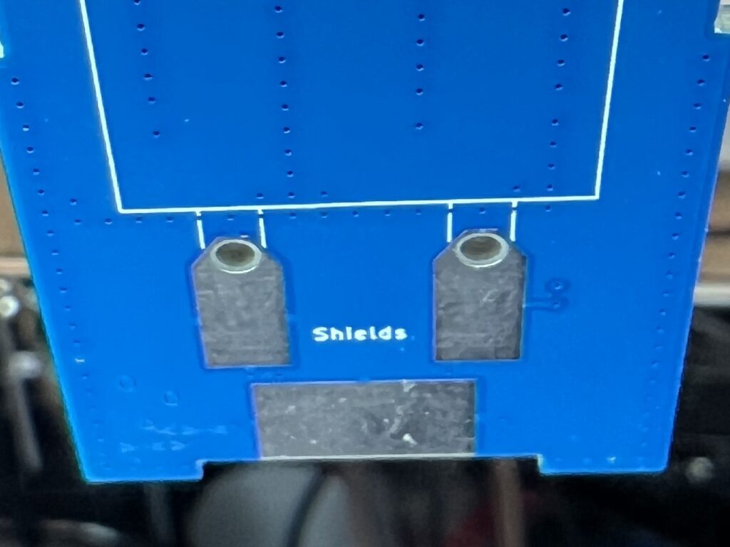
If instead, you see a shiny surface, like the larger solder pads labeled “Shield” continue over the edge and down through the hole, then your board has the problem.
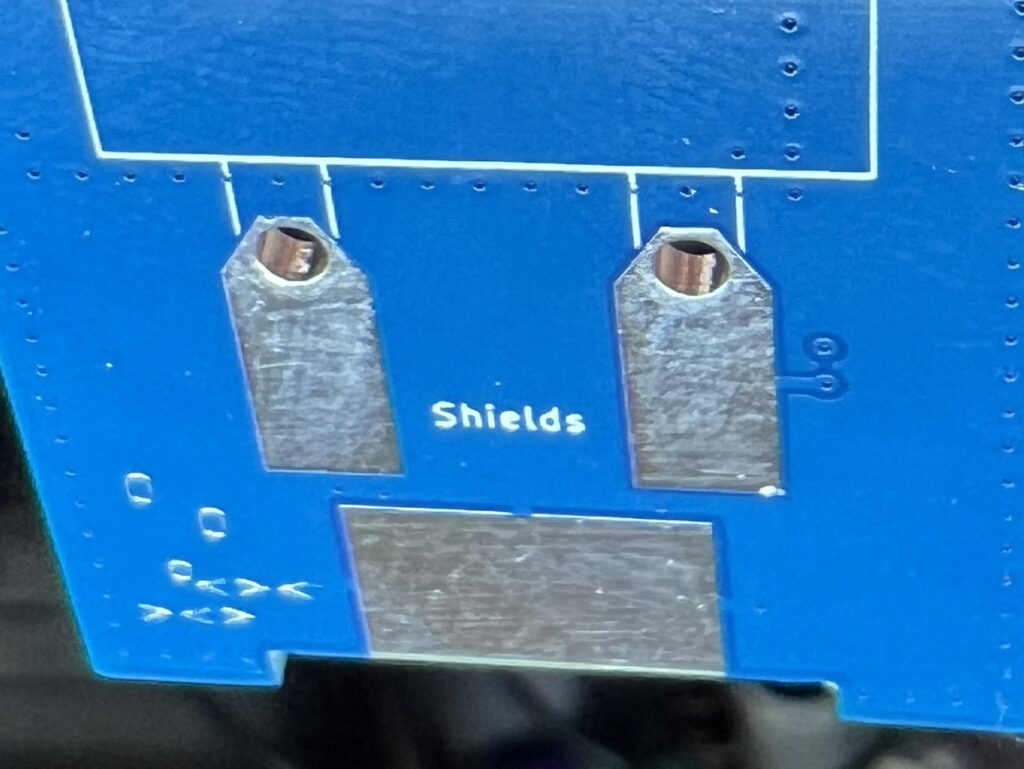
If you see the shiny holes, then your board has this problem and needs to be fixed before you build it.
Note: The unassembled board will NOT test as a dead short between the center conductor and shield of the feed point, like discussed above. The copper layers don’t actually touch, they’re just REALLY CLOSE to each other, and are very likely to be bridged when you solder the shield of the RG316 down to the board.
I have an unassembled board with shiny holes. What do I do?
The short answer is: drill out the holes. Use as small a drill bit as you have that will get the job done. The ideal sizes (in order of preference) are:
- Imperial: 5/64 inch, or 3/32 inch, or 1/16 inch
- Metric: 1.75mm, or 2.0mm, or 1.5mm
If you only have 1/16″ or 1.5mm, they will be a bit smaller than the hole. You’ll need to wiggle the spinning drill bit around in the hole to get all the plating off. It only needs to be enough so that it won’t short to the “Center” pad when you solder the RG316 down.
It’s ok to go a bit larger than the hole (3/32″, 2mm) because there’s nothing on the inner layers at these holes. What you see on the outer layers is all you’re drilling into, and it can handle larger holes, no problem.
I’ve drilled the holes out, and now there is no more plating. What do I do now?
That’s it! Your phasing board is as it was designed. Assemble your kit as per the Assembly Guide: https://halibut-electronics.github.io/EggNOGS/EggNOGS%20Assembly.pdf
Something didn’t go quite right. I need help!
If you’ve run into problems with any part of this, or just have questions, or need more clarification, or whatever, please reach out to support-eggnogs@electronics.halibut.com. We’re here to help out however we can.
73 de N6MTS
-Mark
FAQ:
Q: I have an EggNOGS for a different band. Might I have this problem?
A: The only phasing boards I’ve found with this problem are for 436.5MHz. If you have a phasing board for a different band that shows this problem, please reach out to me to let me know.
Q: What determines whether my EggNOGS kit has this problem or not?
A: The batch of boards in question were purchased in late March 2025. I don’t think I started shipping those boards until Fall, but I can’t be sure. I didn’t track which boards from which batches were shipped out when. To play it safe, I’m saying “Any EggNOGS bought April 2025 or after.” I do know there were 100 boards in the order, I still have 56 that haven’t been shipped, and I’ve built a few. So there should only be about 40 in the wild.
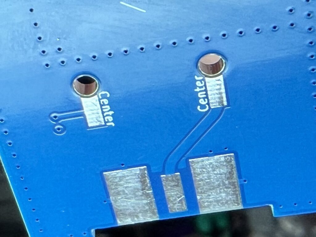
Q: I noticed the holes were shiny on my board (or some other way know I have an offending board), but my assembled antenna is performing ok. Is that expected?
A: It’s certainly possible, yes. It’s not a guarantee that the offending boards will cause a short. As shown in the third image above, the two pads are not directly connected, but they are awfully close. You might have just gotten lucky. I have gotten lucky with one build I made recently, but was not-so lucky with a second one I made today (2025-12-19), when I found this problem.