These are kits that requires assembly by the user. Assembly instructions are here: RF CMCC and Digi CMCC. There’s also a User Guide, covering how to use both the RF and Digi kits. Pre-assembly of the kit is available for $25. It shows as “backordered,” but that only means it’ll take a few extra days to ship because we have to assemble it for you. If the “kit” shows as in-stock, then the “pre-assembled” is also in stock, but will ship a few days later.
Do you have RF in your shack?
Do your lips tingle when they touch your microphone when you key up? Does the Ethernet or USB connection to your radio drop when you start transmitting? Or maybe, you can tell by the noise on 40m, when the LED lights are on in the bedroom that your coax runs through. Or the laundry machine creates hash across the entire waterfall display.
If you identified with any of these problems, you need to clamp some ferrites on the cables in your shack, make some Common Mode Current Chokes. But how do you know how well that ferrite is working? If you add a couple turns of cable to the ferrite, does that make it better, or worse? You could try to measure it on a VNA, but that just measures the insertion loss of the choke, the INSIDE of the coax. It doesn’t measure the effectiveness of the choke itself, which is acting on the OUTSIDE of the coax.
Common Mode Current Choke Test Rigs
The CMCC Test Rig kits allow you to measure the effectiveness of Common Mode Current Chokes (CMCCs) using a VNA. You can quantify the attenuation and/or resistance of a choke, instead of just trusting Internet Wisdom(tm) and hoping for the best.
This video, originally presented at the QSO Today Ham Expo, Fall of 2021, explains in much more detail than I can go into here: common mode currents, where they come from, why we don’t want them, and how to get rid of them. These CMCC Test Rigs are the improved versions of the test rigs used to collect the measurements presented in that video.
How does it work?
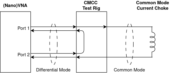
It takes the signal from the inside of the coax (called Differential Mode current) and puts it on the outside of the coax (making it Common Mode), then runs it through the CMCC you’re measuring, and puts it back on the inside of the coax (make it Differential again) to send back to the VNA to be measured:
What is “Good Enough?”
For a common mode current choke, you want as much loss in S21 LOGMAG (attenuation, measured in dB) as possible, across as much of the intended frequency range as possible (eg: the HF spectrum.) Ideally, it would be at least 25db of loss (an S21 LOGMAG of -25db) from 3MHz to 30MHz. More loss is better.
What’s the difference between the RF CMCC Test Rig, and the Digi CMCC Test Rig?
There are two versions of the CMCC Test Rig:
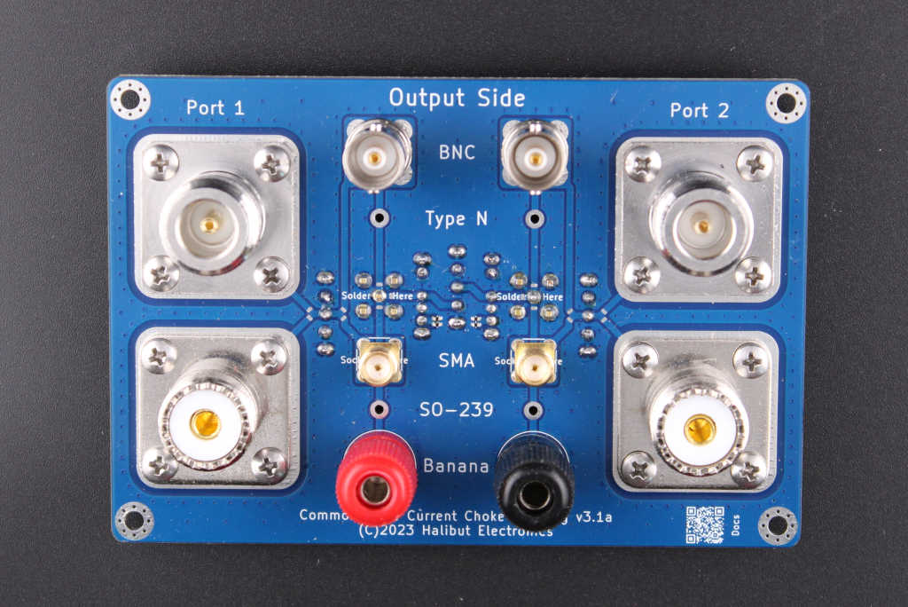
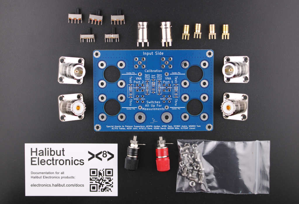
- RF CMCC Test Rig: with BNC, SMA, SO-239, and Type-N connectors. This is the one we’ve been selling since 2022.
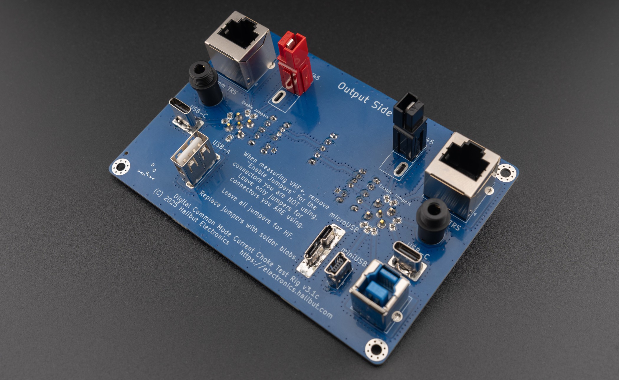
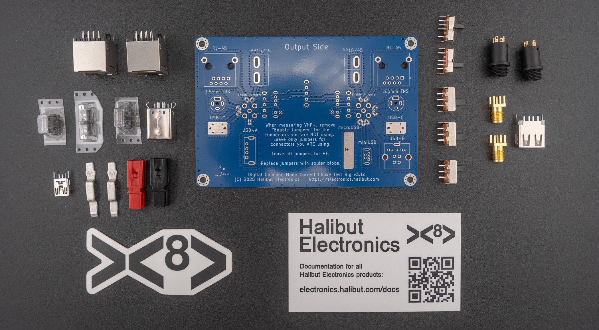
- Digi CMCC Test Rig: with Ethernet, USB, 3.5mm Audio, and Anderson Powerpole connectors. (The word “Digital” is used loosely.)
Other than the connectors, they operate the same. They just let you measure different types of cables.

Terry –
If I can build it (and be pleased with the result) then anyone can. Clear instructions, “good quality ingredients” just take it steadily, and all will look very professional on completion. The price is fair as well.
Mike/KD6FTR –
I finally got around to building the thing after purchasing it straight from the creator at Hamvention. It was super simple to assemble.
Thanks for putting this together Mark!
Now to wait for the station console to be designed/built so I can spend more money to support you.
Matt N3AR (verified owner) –
I just built the digital test rig (and had built one of the RF test rigs a while ago). The build was easy with clearly written instructions, and I only burned myself once!
Corey VK7CH (verified owner) –
Brilliantly designed, superb components and a straight forward job to assembly and straight into testing.
Mark’s kit is a boon for the station owner who is chasing several solutions to knock down stray common mode noise in the shack.