I just launched the Halibut Electronics Broadcast Interference (BCI) Filter for VHF/UHF. It’s designed to prevent strong AM broadcast signals from blowing out the front-end of wide band receivers that have little or no pre-selection, such as inexpensive SDRs. There are many BCI filters availble, but all the ones I could find were designed for HF, and performed very poorly at VHF/UHF. So, I fixed that. 🙂
The posed question:
Curtis KC5CW asked on my groups.io list: “Does it have a power rating or have you tested digital carrier/fm vs ssb?”
Thank you for the question, Curtis. The immediate answer is: No, I haven’t tested any power handling. I designed it with receive in mind so power handling wasn’t a design requirement, or even consideration.
Having said that…
- It uses Murata parts.
- Murata publishes S-parameter files for their components.
- Qucs can make a component from an S-parameter file.
- Qucs can graph voltage and current over frequency for individual components, to compare against their ratings.
We have all the parts we need to simulate the answer to your question. Let’s do this thing!
The schematic:
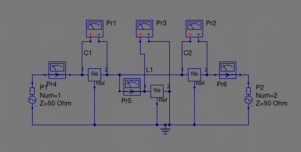
This is what I drew up in Qucs:

The three “File” blocks are the components, with the S-parameter files loaded. Voltage sensors wrapped around each component, and current meters in every wire. Port 1 on the left, Port 2 on the right. Doing an “S parameter” simulation to measure the frequency response, and an “ac simulation” to get voltage and current measurements for each component.
One point twenty one JIGGAWATTS!
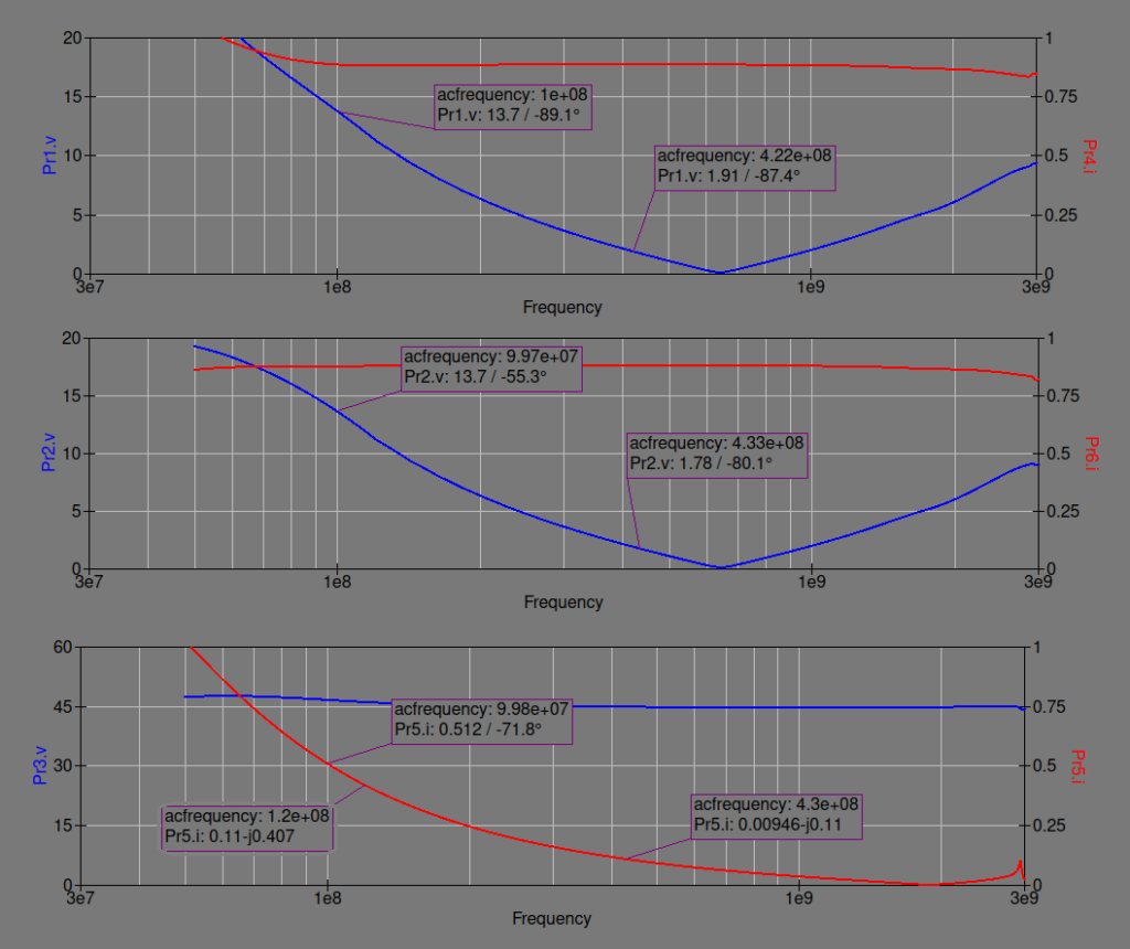
I was going to write up the whole process of getting a result, all the different power levels I tried and measurements I took, but it doesn’t really matter. Long story short, here are the graphs at 43dBm (20W). Top is C1 (input), middle is C2 (output), and bottom is L1 (shunt). Voltage on the left in blue, current on the right in red.

The important parts to observe are:
- The capacitors are rated at 50v, so they’re well within their limits.
- The inductor is rated at 420mA, which it hits at about 120MHz when transmitting 20W.
The ratings below VHF aren’t as important because you’re not putting power through the filter at those frequencies; it’s only seeing the power come in from that strong AM station at those frequencies, which should be mW at most. (If you’re seeing 20W of power coming IN your antenna, you’ve got bigger problems. 🙂
The current in the inductor is our limiting factor. Here’s the graph at 46dBm (40W):

2 meters is out of range (greater than 0.42A) at 40W, but everything in UHF should be safe. (They’re not shown here, but the capacitor voltage ratings are still well below their limits.)
Conclusion:
What does all of this mean? Well, it means that even though the BCI Filter for VHF/UHF was designed for receivers, it can take some moderate transmit power too:
- 6m and 4m are out. You can probably get 1 watt through it, but I wouldn’t go higher than that.
- 2m is the limiting factor. 10W at 2 meters is pretty close to the limit, but within it. 5W is safe though.
- 1.25m, 70cm, and higher are safe up to at least 40W. The component values are still safe at 100W (highest I simulated), but I would start to worry about the PCB at that power.
Disclaimer: I HAVE NOT TESTED THIS!
This is all based on simulations and published component values, not real-world measurements. While I can’t warranty BCI Filters that have been transmitted through, I WILL offer this:
Test For Me:
If you do a test, measure the temperature rise from a given power at a given frequency, determine the breaking points, etc. and then share that data with me (either publicly published, or privately to me; your choice), then I absolutely WILL replace any BCI Filters damaged during that testing. Not quite a warranty, more like subsidized 3rd party testing.
That’s it for now. Back to working on EggNOGS. Thank you all so very much for your continued support!
Cheers, 73 de N6MTS
-Mark
