I have written about how to make a Simple OHIS Radio Adapter for Icom Radios before. But I’ve recently received a couple folks asking me:
“How do I connect my Halibut Electronics Radio Pro to an Icom IC-705?”
The problem is that the IC-705 works more like an Icom HT than an Icom HF or Mobile rig. Icom HTs (and most manufacturer’s HTs actually) trigger PTT not by a simple contact closure to ground, but by completing the microphone circuit. It’s an entirely different method that can’t easily co-exist with the other configurations on the same board. The Radio Pro Config Board for the Icom won’t do it natively, it needs a bit of tweaking.
What tweaking do I do?
Headphones/Speaker:
Use a standard 3.5mm TRS cable between the [SP] port on the radio, to the Headphone/Speaker port on the Radio Pro. Nothing special, this isn’t the hard part.
Microphone:
This will use a somewhat unique cable that I will make available in my shop, a 3.5mm to 2.5mm TRRS cable. It will connect between the [MIC] 2.5mm port on the radio, and the Microphone 3.5mm port on the Radio Pro.
Config Board:
This is the fun part. You will be removing and placing some solder-bridge jumpers on the Config Board, and placing one 33k surface mount resistor. It can be either an 0603 or 0805 resistor, power handling and resistor type (thin or thick film, etc) don’t matter. Alternatively, you can get creative with some needle nose pliers and use a through-hole resistor with leads bent into little “feet” and solder to the pads.
A bit about the Config Board: It has a grid of jumpers. Every row is a pin on a connector, every column is a signal. You attach a signal to a pin by dropping a solder-blob at the correct intersection. I will specify that intersection as: Pin/Signal. For example, “Ring2/Mic-” will place Mic- on Ring2 of the TRRS connector.
The pick’n’place machine at assembly can’t place a literal solder blob, so it uses zero ohm resistors instead. If you need to remove a zero ohm resistor, just heat one side long enough to heat soak the component and pad. Then heat the other side and gently lift up with the soldering iron. The component will come up without too much force. DO NOT FORCE IT as you risk lifting a pad off the board. Worst case, you can use fine diagonal cutters to break the zero ohm resistor, and remove the two halves separately. Don’t worry, you don’t need to save this component. It can go flying off into the carpet, as SMT components are wont to do, we won’t be using it again. When you need to place a jumper, you’ll do it with a blob of solder.
This image will help you find what I’m talking about:
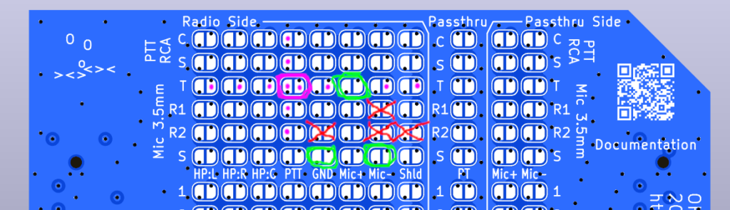
- Find the four “Mic 3.5mm” rows. They will be near the top of the Config Board, just below the two rows for the RCA PTT socket. They are labeled: T, R1, R2, and S.
- Remove any jumpers at: Ring2/Mic-, Ring2/GND, and/or Ring2/Shield. (Red X’s)
- Remove the jumper at Ring1/Mic- (Red X)
- Leave the jumper at Tip/Mic+ (Green circle)
- Add jumpers to BOTH of: Sleeve/Mic-, and Sleeve/GND. (Green circles)
- Solder a 33k ohm resistor across Tip/PTT. (Magenta circle)
- An 0603 or 0805 resistor will fit here.
- Alternatively, you can use a through-hole resistor, and solder its ends to any of the pads with a Magenta dot on it. Note that the left pads in a column are all the same, and the right pads in a row are all the same.
Once this is done, then follow the normal instructions for the calibration and tuning of the Radio Pro.
What if I am not using a Radio Pro, and I just want to make my own OHIS Cable for my Icom IC-705?
The neat thing about Icom and OHIS is that Icom radios are already OHIS compliant, electrically. They output headphone level receive audio like OHIS, and take an electret microphone like OHIS. The HF and Mobile radios use a simple contact closure to ground like OHIS. See this post if you want to learn more about making a direct cable for Icom HF and Mobile radios.
But, as discussed above, the HTs don’t do PTT the same way. If you want to make a direct cable for an IC-705, then you will need to do the same thing we did above: place a 33k ohm resistor between Mic+ and PTT on the OHIS side of the cable. And, of course, it’s an entirely different pin-out between the GX16-8P, and a 3.5mm and 2.5mm connector.
Here’s the new pin-out matrix:
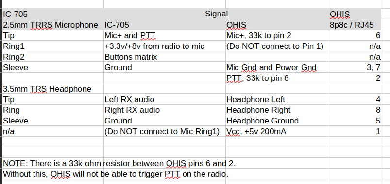
I haven’t built one and tested this myself, but it should work. If you build this, please Contact Us and let me know if it works for you.
Cheers, 73 de N6MTS
-Mark