NOTE: The HHI Radio Pro comes with one Config Board included in the price, selected when you add the HHI Radio Pro to the Cart. Only purchase this item if you want an additional Config Board to replace, or swap out, the Config Board that came with your HHI Radio Pro.
The Config Board for the HHI Radio Pro specifies which signals are on which pins (with solder-blob jumpers), and what levels those signals are (with trim-pots). The configuration for a particular radio is contained entirely on the Config Board, and the Radio Pro is entirely generic. This allows the user to move the HHI Radio Pro from one radio to another by simply swapping the Config Board.
Halibut Electronics sells Config Boards pre-configured for several common types of radios (see Config Board Preconfigurations tab below for details,) and also a Generic board with no radio-specific configuration already applied. Note however that ALL Config Boards (even ones that have been pre-configured) can be re-configured by the user.
Config Board Pre-configurations
There are 4 available pre-configured HHI Radio Pro Config Boards, plus 1 “Generic” board that has not been pre-configured. If your radio is not supported by one of the 4 pre-configured boards, you can buy the Generic board and configure it yourself; see the HHI Radio Pro User Guide for details on configuring the HHI Radio Pro Config Board. NOTE: You can re-configure any Config Board, even a pre-configured Config Board, to support any radio. So if you buy the wrong board, or need to make some modifications for whatever reason, ANY Config Board can be made to work with any radio by following the instructions in the User Guide.
How The Configuration Is Made:
Note how the Config Board is a large grid of solder pads. Some solder pads have small black “zero ohm resistors” on them, and most of them are open. The user can make jumpers with a blob of solder; the 0 ohm resistor is just a “blob of solder” that can be automated with a pick-and-place machine at manufacturing time.
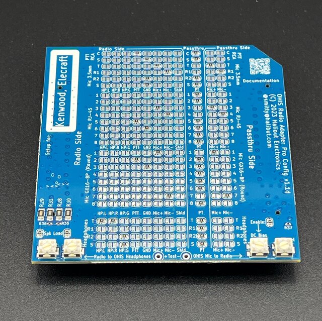
For the purposes of figuring out which board to use for which radio, you can ignore the trim-pots along the bottom, as well as issues like “Dynamic vs Electret” microphone, “Speaker vs Headphone” output, etc. Those are the same for every Config Board option, and are handled by the User at installation. See the HHI Radio Pro User Guide for details.
On this grid of jumpers, the rows are the pins on connectors, such as “3.5mm microphone, Tip” or “GX16 microphone, Pin 3”. The columns are signals, such as “Headphones Left” or “Mic+”. A signal is connected to a pin by placing a jumper (either a 0 ohm resistor at manufacturing, or a solder blob by the user) at the intersection of the pin (row) and signal (column).
Toward the right side, there’s a separate column labeled “Passthru” then two more columns labeled “Passthru Mic+” and “Passthru Mic-“. The Passthru column connects the Radio Side connector on the back to the Passthru Side connector on the front. Every pin EXCEPT Mic+ and Mic- are passed through to the Passthru side. The Mic+ and Mic- pins are connected to the last two columns “Passthru Mic+” and “Passthru Mic-“. This is because the HHI Radio Pro needs to select which microphone signal to send to the radio, either the Passthru microphone, OR the OHIS microphone, but not both. All the other signals can be connected in parallel, so they’re just passed through.
The configurations below will document which 0 Ohm resistors are pre-populated by Halibut Electronics for a given configuration, so you can compare with the documentation for your radio to verify which one you should select.
Modular Jack Pin Numbers in Radio Documentation:
Radio documentation is horribly inconsistent in its numbering of modular connector (aka RJ45) pins. Yaesu seems especially bad at numbering pins in their documentation backwards from the accepted standard and they’re not even consistent about it. Because of this, we will be using the accepted standard pin numbers: If you hold the modular jack in your hand, with the contacts facing you, and the cable going out the bottom of your hand, the pins are numbered from left to right. Pin one on the left, pin 6 (for 6p6c) or 8 (for 8p8c) on the right.
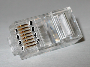
When comparing the 8p8c/RJ45 pin numbers below against your radio documentation, confirm how your documentation is numbering their pins.
All Configs:
Since the majority of the variation between radios happens on the 8p8c/RJ45 and the GX16 connectors, the following connections are on all Config Boards. In fact, these (plus all the Passthru jumpers) are the ONLY connections on the Generic board.
- RCA PTT:
- Center: PTT
- Shield: Radio Ground
- 3.5mm Microphone
- Tip: Mic+
- Ring1: Mic-
- Ring2: Radio Ground
- Sleeve: Radio Ground
- 3.5mm Headphone/Speaker:
- Tip: Headphone Left, and Headphone Right. This is for a Mono source.
- Ring1: Not connected. User move’s Headphone Right to here for Stereo sources.
- Ring2: Headphone Ground
- Sleeve: Headphone Ground
All pins, except pins assigned to Mic+ and Mic-, are connected to the Passthru connectors on the front panel. Only the mic pins are NOT passed through because the HHI Radio Pro needs to switch between the Passthru mic and the OHIS mic, based on which PTT is pressed.
Yaesu HF, or Flex
Select the “Yaesu HF, or Flex” configuration if your radio matches this pin-out:
- 8p8c/RJ45 Microphone:
- Pin 5: Mic+
- Pin 4: Mic-
- Pin 6: PTT
- Pin 7: Radio Ground
- GX16 Microphone:
- Pin 8: Mic+
- Pin 7: Mic-
- Pin 6: PTT
- Pin 5: Radio Ground
Yaesu Mobile
Select the “Yaesu Mobile” configuration if your radio matches this pin-out:
- 8p8c/RJ45 Microphone:
- Note that Pin N on 8p8c on HHI Radio Pro maps to Pin N-1 on the 6p6c on the Radio.
- Pin 3 (2 on 6p6c): Mic+
- Pin 4 (3 on 6p6c): Mic-, and Radio Ground
- Pin 2 (1 on 6p6c): PTT
- GX16 Microphone:
- Pin 8: Mic+
- Pin 7: Mic-
- Pin 6: PTT
- Pin 5: Radio Ground
Icom HF and Mobile:
Select the “Icom HF/Mobile” configuration if your radio matches this pin-out:
- 8p8c/RJ45 Microphone:
- Pin 6: Mic+
- Pin 5: Mic-
- Pin 4: PTT
- Pin 7: Radio Ground
- GX16 Microphone:
- Pin 1: Mic+
- Pin 7: Mic-
- Pin 5: PTT
- Pin 6: Radio Ground
Kenwood HF and Mobile, or Elecraft:
Select the “Kenwood HF/Mobile, or Elecraft” configuration if your radio matches this pin-out:
- 8p8c/RJ45 Microphone:
- Pin 3: Mic+
- Pin 4: Mic-
- Pin 5: PTT
- Pin 6: Radio Ground
- GX16 Microphone:
- Pin 1: Mic+
- Pin 7: Mic-
- Pin 2: PTT
- Pin 8: Radio Ground
Generic:
If your radio doesn’t match any of the above pin outs, then buy the “Generic” board which only has the connections on the “All Boards” at the top. All 8 pins on both the 8p8c/RJ45 and GX16 are just passed through. The user can then jumper the signals to the correct pins for their radio, without having to “undo” any pre-existing jumpers.

Reviews
There are no reviews yet.