Now Shipping!
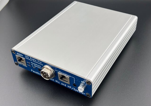
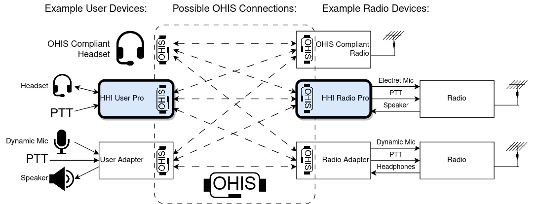
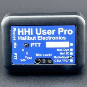
The HHI Radio Pro is an Open Headset Interconnect Standard (OHIS) compliant Radio Device adapter. When connected to a radio, it allows any OHIS compliant User Device, such as the HHI User Pro, to connect to the radio, regardless of its microphone type, speaker type, or PTT method.
See the OHIS Overview tab for more information.
Features:
HHI Radio Pro does everything an OHIS Radio Device adapter needs to do, and more.
Works with every radio:
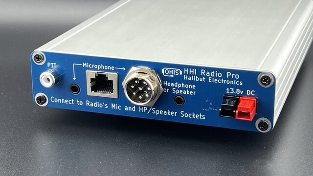
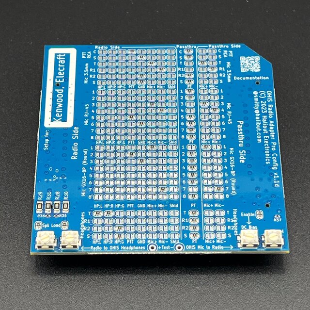
HHI Radio Pro has several physical connector options to match your radio. On the HHI Radio Pro Config Board (included with HHI Radio Pro), any signal can be assigned to any physical pin, allowing for maximum flexibility. See the Config Board Preconfigurations tab for more details.
All audio circuits have sufficient dynamic range to work with all common audio levels. All connections to the radio are galvanically isolated with transformers for audio, and opto-isolator for PTT, preventing ground loops. See Additional Information tab for physical and electrical details.
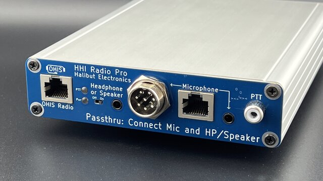
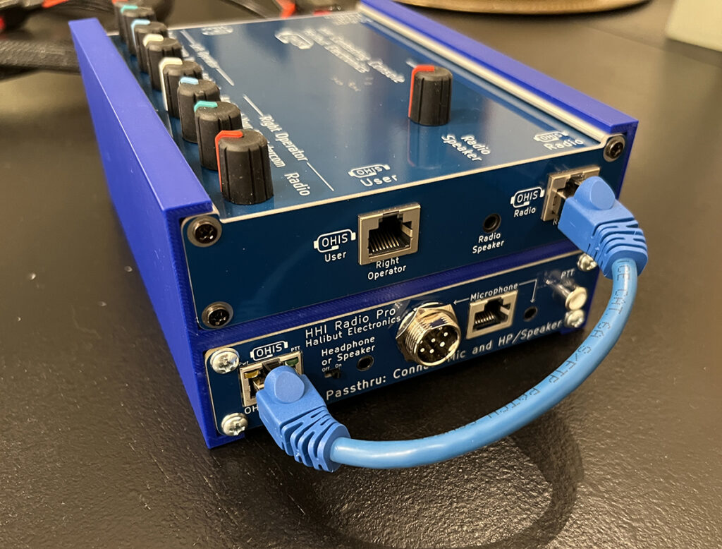
Passthru Ports:
The same connectors used to connect to the radio are also on the front of HHI Radio Pro, allowing you to connect your radio’s stock microphone, headphones or speaker, and PTT. Receive audio from the radio is sent to both the OHIS port, and the Passthru ports. Which microphone audio is sent to the radio is determined by which PTT is used. When OHIS PTT is engaged, the OHIS microphone audio is sent to the radio. All other times (including when no PTT is pressed), the Passthru microphone audio is sent to the radio. All other pins are connected directly from Radio to Passthru ports, preserving their functionality, even of OHIS doesn’t know what it is.
Reviews
There are no reviews yet.